Sunday, April 18, 2010

LED display progress...and problems

Today was a bit frustrating. I made some more progress on the LED display circuit, laid out here:
This circuit is designed to take the 4MHz clock coming off of the EDE707 and use it to drive a couple multiplexers and buffers (I ended up using a pair of 74LS12[56] chips instead of the 74F257). The intended waveform is shown at the top right. The CLK signal (a direct down-clock of the 4MHz) will be used to drive the LATCH pin of the EDE707. Qa will be used to select which set of inputs to use (address pins, or Qb/Qc/0/0). Qb and Qc will be used to drive the multiplexers so that the right part of the input shows up on the EDE707 inputs at the right time. Easy, right?

Here's what the program counter board looks like now:
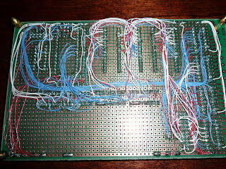
Here's a front view with the various sockets/chips described.

So far so good, right? Well, not so much. After wiring up the 2:4 multiplexers and the quad tristates, the program counter board is now suffering from a bug such that all outputs are now held high all the time. No freaking idea why. I spent half an hour with a multimeter trying to find something resembling a short circuit, and couldn't find one.

I thought maybe it was some weird situation where a "high" output was wired to a "low" output and was thus causing a short, so I pulled all of the ICs out of the board. But even with no ICs in the board, it's still sending all of the outputs high. Which is even more bizarre, because the various output pins are isolated from each other (even more so with the ICs removed). So why would they all register +5v when the board is plugged in, even when there are no ICs in the board?

The other possibility is that my logic analyzer is no longer properly calibrated. I did notice that it said "default calibration settings loaded" the last time I booted it up.

So more research and debugging is to come. For now, however, I effectively have a paperweight that I spent a dozen hours to create. Lame.

Saturday, April 10, 2010

More progress on the program counter

Got some more wiring done today. At my last update, I had the "counter" part of the program counter done, but hadn't wired up the address pins of the EEPROMs. I've now cascaded the address pins to all three EEPROMs (32 wires, 64 solder joints) and also cascaded the address pins to a pair of 4052 dual 4:2 multiplexers. Why?
The multiplexers are part of a state machine that will be used to drive the EDE707, which I also added to the board today. The EDE707 is a pretty cool little chip -- it can drive 8x 7-seg LED displays using a microprocessor-style input. This is part of the "cool blinky lights" part of the project -- I want to have a 4-digit LED display of the current instruction. It'll be handy for debugging at slow clock speeds, and it'll look cool too!


The EDE707 runs at 4Mhz (that's the crystal sitting to the top-right of it). However, it's pretty pokey with respect to command inputs. To set the displays, you first setup a command on the four input pins (ex: 0010 for the third digit), then bounce the latch pin. Then you setup the value for that digit on the input pins, and bounce the latch pin again. Unfortunately, the datasheet says you have to leave the data active on the pins for 1.2ms (milliseconds!) after bouncing the latch. When your clock is running at 4Mhz (250ns), 1.2ms is an eternity.

The way I've decided to accommodate this is to build a simple state machine. The 4MHz clock first goes into a 12-stage ripple counter. This gets the clock pulses down to ~2ms between high-low transitions. This slower clock then goes into a 4-bit synchronous counter. The counter is used to run through a simple state machine:
  1. Counter: 0000: send 0000 (first digit) to the input pins
  2. Counter: 0001: send a0, a1, a2, a3 to the input pins
  3. Counter: 0010: send 0001 (second digit) to the input pins
  4. Counter: 0011: send a4, a5, a6, a7 to the input pins
  5. Counter: 0100: send 0010 (third digit) to the input pins
  6. Counter: 0101: send a8, a9, a10, a11 to the input pins
  7. Counter: 0110: send 0011 (fourth digit) to the input pins
  8. Counter: 0111: send a12, a13, a14, a15 to the input pins
As you can see, I can use the least-significant bit of the counter to drive a 2-input multiplexer that selects between a 4-bit piece of the address, or a command.

The commands can be driven directly from the counter -- the second and third bits are used to form the last two bits of the command.

Finally, the address information is formed by passing the address information through four 4:2 multiplexers, using the second and third bits of the counter as the selector.

When all said and done, each piece of the command takes about 2ms due to the many counter stages. Thus to get through all eight steps takes about 16ms. However, this still results in an effective polling rate of around 60Hz, which is much faster than the human eye can even perceive.

I've still got quite a bit of work to do before the program counter is done:
  1. Add the final multiplexer to drive the input pins of the EDE707
  2. Add the LED display and its driver transistors
  3. Finish wiring up the EEPROMs (I still haven't even run power and ground lines to them)
  4. Install the address load socket and wiring
  5. Install the current instruction sockets and wiring
...and then on to the shift/jump unit!